Construction & Engineering

Engineering software needs to understand how design decisions produce the drawing.

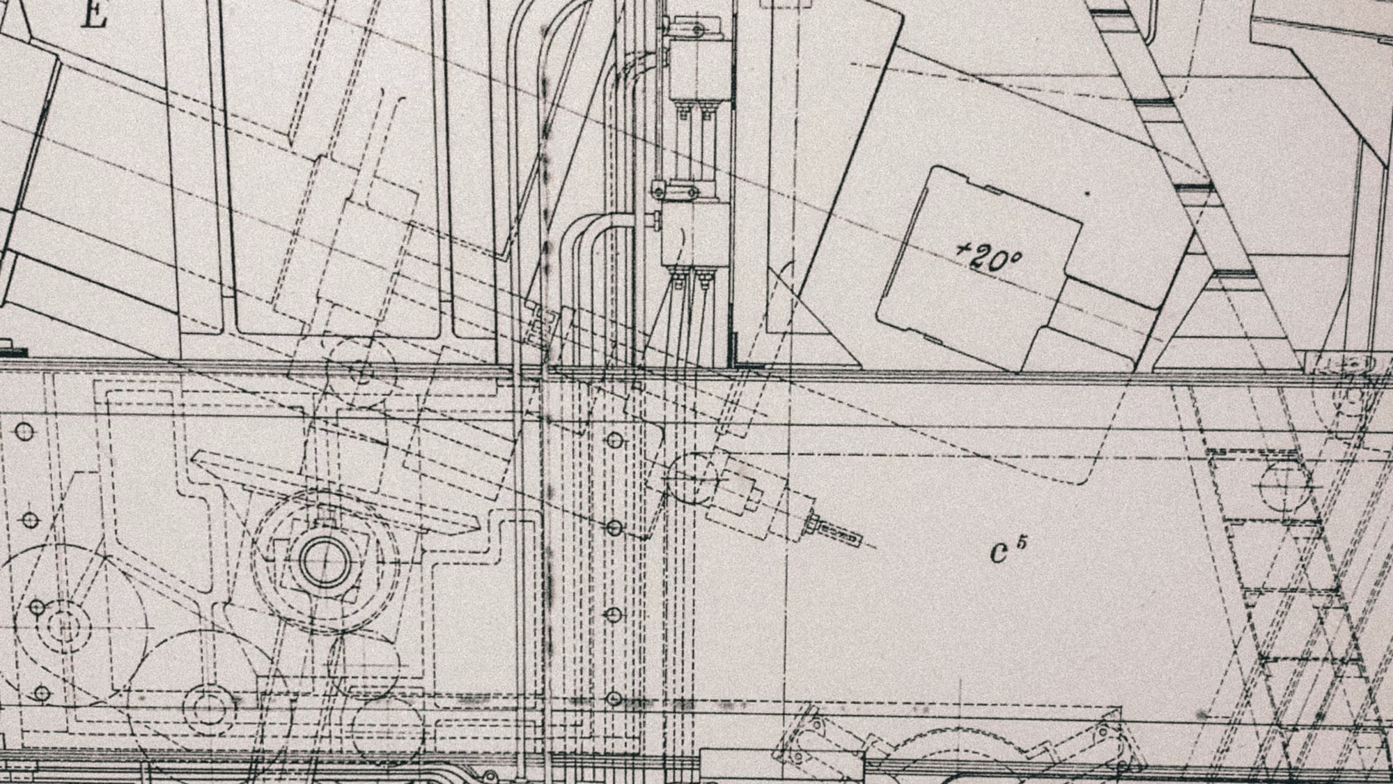
Technical engineering drawing with linework, dimensions and machine detail

A drawing records the result of many engineering decisions

Before a technical drawing can be produced, someone has interpreted the requirements, understood the physical setting, applied the relevant standards and checked whether the proposed design will work.

The design also has to be practical to fabricate and install. A technically valid solution may still be unnecessarily expensive or awkward to build.

Software that treats the drawing as an isolated deliverable misses the decisions and relationships that determine what belongs on it.

Requirements have to become design decisions

Tender and project documents describe what must be achieved, but they rarely determine the complete solution. Geometry, site conditions, interfaces, dimensions and applicable standards still have to be translated into a design.

That translation is where engineering judgement enters the workflow. The system needs enough context to distinguish a requirement from the design choice made in response to it.

Engineering rules limit what can be built

Loads, material properties, allowable limits and structural checks constrain the available design choices. They cannot sit in a reference document that the software never uses.

For automation to be reliable, the relevant calculations and rules need to form part of the working model and remain traceable to their source.

Passing the checks is not enough

Consider a noise barrier. Post spacing, panel dimensions, foundations, connections and material choices affect one another. A design may pass its structural checks and still create avoidable fabrication work or be poorly suited to the site.

The system needs to account for how the assembly will be manufactured and installed, along with the technical limits that make it safe.

Drawings change when the design changes

Geometry, calculations, components and design choices are connected. Changing one dimension can affect several components, checks and drawing views.

Useful CAD automation models those relationships so that downstream outputs can change with the design. Treating each drawing as an isolated document simply moves the coordination work elsewhere.

Design implication

What this means for software

Engineering software has to represent the constraints, calculations and relationships behind the artefact it produces.

Mesograde starts by learning how requirements become design decisions and how those decisions affect fabrication, installation and technical outputs. Drawings and other deliverables can then be generated from a model that reflects the engineering work behind them.
A practical place to start

Start with one bounded design package: the source requirements, the calculations, the drawings they produce and a few revisions that changed the outcome.

Mesograde can trace the relationships between them and identify which parts of the work are stable enough to support with software.

Discuss this workflow

Related work